

Yelo Test Fixtures & Jigs
Fixture Base
Probe Plate (undrilled)
Stripper Plate to protect probes when no PCB fitted
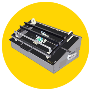
Ground Plate
Top Hat & 3 Chessbars
24 Pusher Feet, 8 Per Cross bar to push PCBs onto Probes
Interested in getting a quotation for a Yelo test fixture or need more information?
- Get a quote
- Request more information
Yelo Testpoint PCB Loading Test Fixture
Yelo Test Fixture Probe Close-up
What is a test fixture?
A test fixture or test jig is the component containing the bed of nails used for testing the PCB or assembled product. It is powered and controlled by the Yelo Testpoint system which has test cards capable of providing multiple test conditions. This system also controls the probes used in the bed of nails, and relays test information back to the Testpoint system to be analysed.Yelo test fixtures can be used for edge connector functional testing. In this case, the link between the unit under test (UUT) and the edge connectors is made via a set of cables. This provides an alternative method of testing compared to horizontal bed of nails testing, or vertical bed of nails where the probes are linked via channels to relay test cards.These fixtures can either be mechanically or pneumatically operated. The mechanical test fixtures require the user to manually close the test fixture's top hat on the PCB, holding it into place. This activates the bed of nails, pressing it against the PCB. Due to the mechanism involved, the mechanical test fixtures are cheaper in comparison to the pneumatic test fixtures.
What type of fixture do you want?
Mechanical
Mechanical test fixtures have a limit to the number of probes that can be used in testing. As the number of probes increases, the force required to push down onto the PCB also increases, causing difficulties for the user. Therefore there is a limit of around 100 probes in this style of mechanical test fixture.
Mechanical Cam
There is a new lever action, mechanical cam test fixture which allows for an increase in the number of probes that can be used. This maintains the advantage of lower costs while improving the number of probes that can be used for a more flexible test.
Pneumatic
The pneumatic test fixture uses an air compression system to hold the PCB onto the probes for testing. These can be pushed either up onto the PCB or down onto it depending on pin orientation. This means the limit to how many probes that can be used is controlled by how many available channels there are.
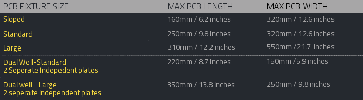
Dimensions
How to Complete Your Fixture
Simply drill holes on your CNC for the pogo pins in the probe plate to match up with your PCB, fit and wire the pogo pins and mount any additional golden unit PCBs, microprocessor programmers or instruments inside.
